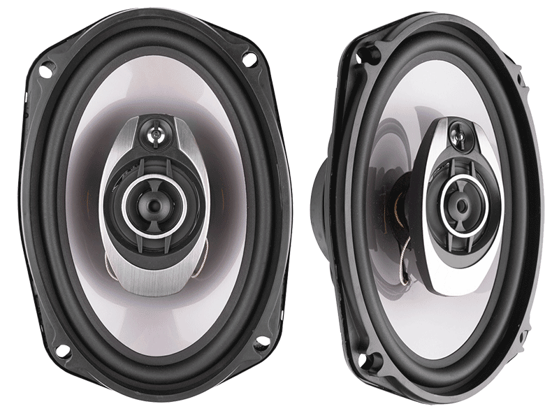
 We all know that the performance of different makes and models of speakers and subwoofers has a dramatic difference in how they sound. When it comes to the installation of subwoofers, the choice of enclosure plays a huge role in the sound of the subwoofer system. In this article, we look at some of the benefits of custom vented enclosures and solutions available.
The Factors that Determine Performance.
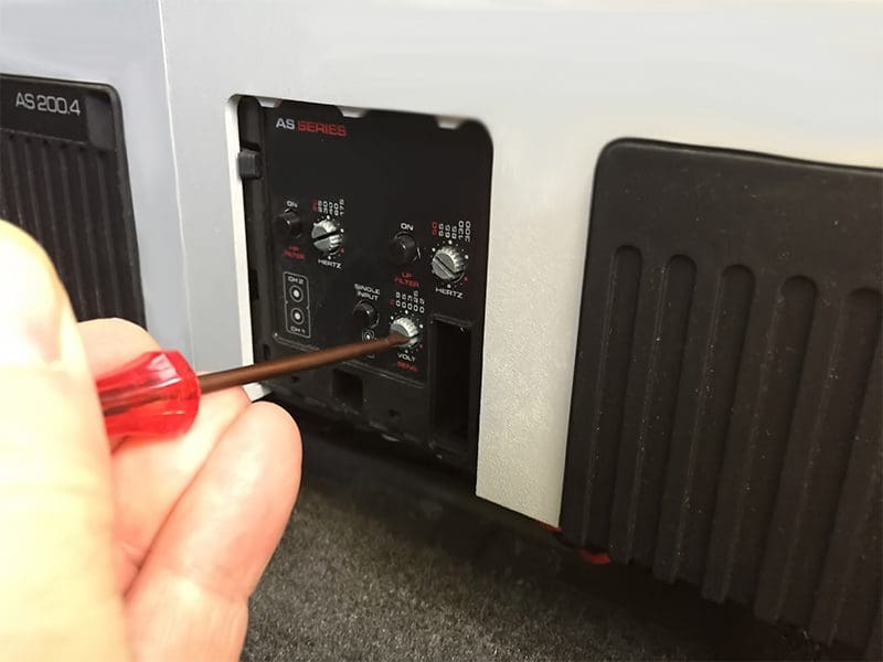
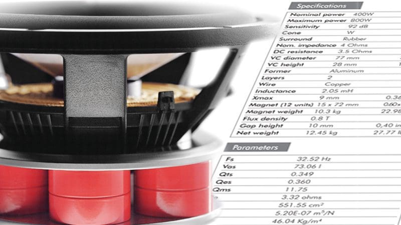
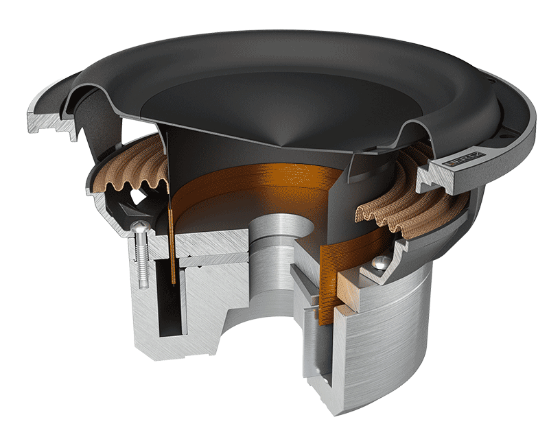 Three criteria have the most effect on performance: air volume, tuning frequency (for bass reflex enclosures) and construction. Every subwoofer has its electro-mechanical characteristics. Subsequently, each subwoofer needs its very own enclosure design. With that said, some relatively standard designs offer good performance across a wide variety of speakers.
The difference between having an enclosure that “works” and one that sounds amazing is all in the design. Have your mobile electronics retailer confirm that the air volume and tuning frequency match your application before you purchase. (We will explain that happens when the air volume or tuning frequencies are “off” in another article.)
Wait, Why Vented Enclosures?
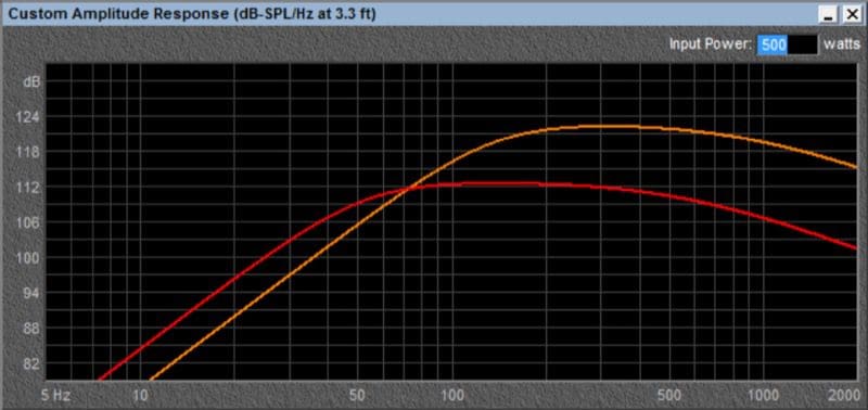
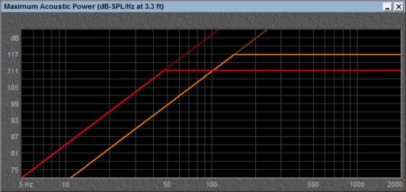
While there are benefits and drawbacks to each type of enclosure, a vented (bass reflex) enclosure will offer excellent efficiency and low-frequency extension for most people. These enclosure characteristics reduce the amount of power we need to send to the woofer, and therefore reduce the chances of overpowering and damaging the woofer.
Off-the-shelf Enclosures
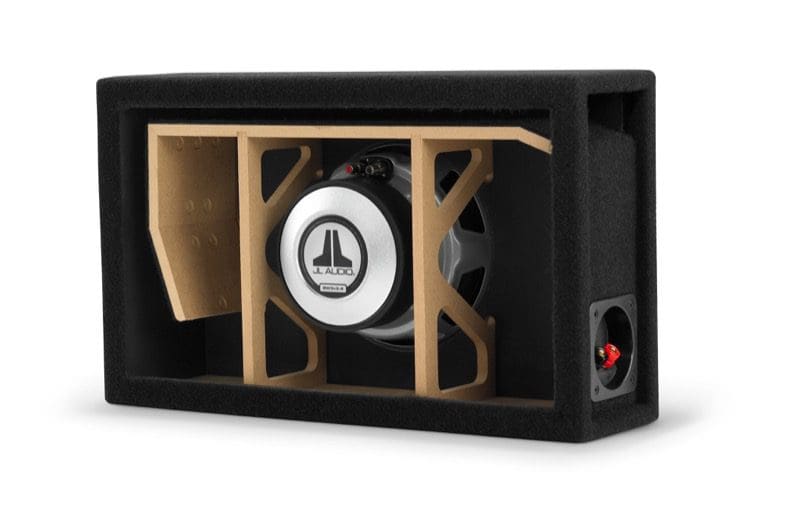
Many car audio retailers offer subwoofer enclosures that have been mass-produced. These enclosures vary dramatically in construction quality and design. Some companies tune their enclosures relatively high to increase efficiency at higher frequencies while sacrificing low-frequency output and power handling. The materials used to build these enclosures also vary in quality.
Almost all of these off-the-shelf enclosures are made of MDF. That said, the density of the material varies a great deal. Some MDF is very soft in the middle, offering less resistance to panel deformation. Enclosures made of this soft-center MDF are also prone to having the mounting hardware strip when your installer goes to mount the subwoofer.
These days, efficient use of space is increasingly important for auto sound enthusiasts. An off-the-shelf enclosure may not maximize the available space in the storage area of your vehicle. Enclosure manufacturers try to balance the dimensions of the enclosure against the airspace requirements of the intended driver and the space available in the average vehicle.
Construction Methods
Many enclosure manufacturers claim to use a rabbet joint where two panels meet. Unlike a butt joint, a stepped rabbet joint will increase the surface area of the connection by about 50%. Enclosure assembly typically makes use of a generous amount of glue. Once glued, the panels are held together with brad nails to allow the glue to set up. The additional surface area provided by the rabbet connection results in a stronger joint and a reduced chance of air leaking.
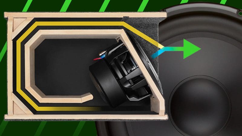
Vent Considerations
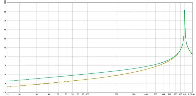
If a vent (or port) is designed and constructed properly, a vented enclosure can produce less distortion than a sealed (acoustic suspension) enclosure. To reduce distortion and meet these goals, the vent must have adequate surface area and be designed in a way that the air entering and exiting the vent will couple well with the air in the listening environment. Several subwoofer manufacturers design and construct their enclosures. These stand out from the crowd as having excellent vent designs.
Enclosures with no radius or taper on the vent end are more prone to noise. This sharp edge on the vent can create chuffing or other noises as air rushes over its edges. For a 3-inch or larger vent, a simple 3/4”-inch radius on the vent edge is just barely enough to be beneficial. A much larger radius offers more benefit in allowing the air inside the vent to decelerate properly.
Your Enclosure May Need Bracing
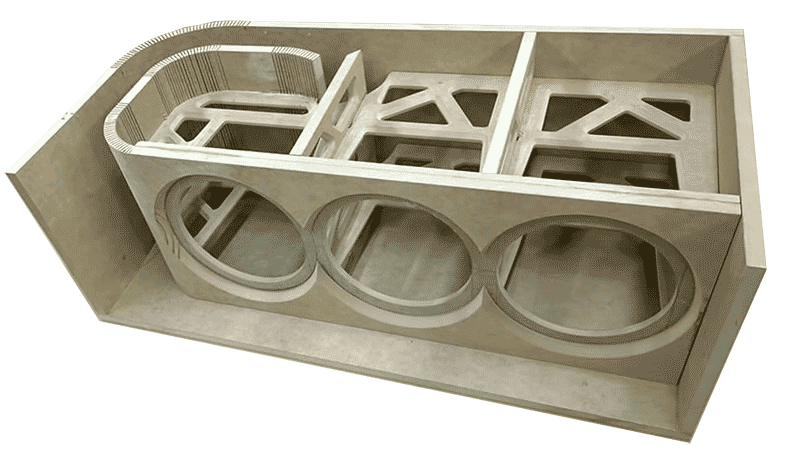 If you are looking for the best possible performance from your subwoofer system, then every effort possible should be made to ensure that each panel of the enclosure is as rigid as possible. One way to add strength to an enclosure is for the manufacturer to install bracing. Bracing connects opposite panels to each other to reduce flexing. Panel vibrations can, in extreme cases, cause glue joints to fail.
Application-specific Subwoofer Enclosures
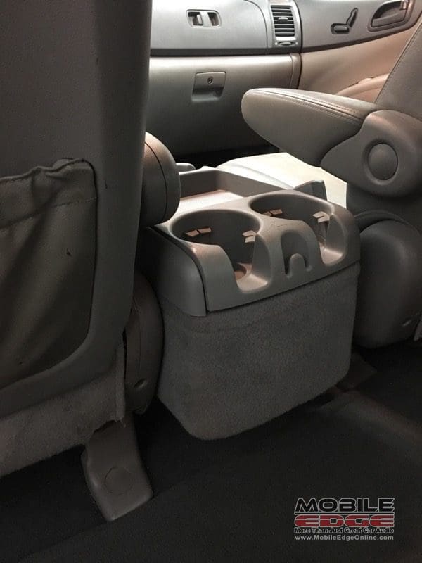
We have talked about some of the benefits and some of the drawbacks of an off-the-shelf subwoofer enclosure. The alternative is to have your mobile electronics retailer design and construct an enclosure to fit your vehicle. Maximizing usable storage space can be achieved by having your fabricator fit the enclosure snugly to the sides of the vehicle. Many vehicle-specific enclosures combine different construction techniques. Flat panels, fiberglass, stacked-panel fabrication and more can allow an installer to make amazing use of every cubic inch of your storage space.
Maximize Bass Custom Vented Enclosures
One of the first and most beneficial additions than can be made to a factory audio system is a subwoofer system. When it is time to take that first step, visit your local mobile electronics retailer. They will be happy to show you what is available for your vehicle, and what they can create. We know that no matter what you choose, you will be pleased with the dramatic results.
This article is written and produced by the team at www.BestCarAudio.com. Reproduction or use of any kind is prohibited without the express written permission of 1sixty8 media.